Electric Circuit Studio

Electric Circuit Studio Summary
Electric Circuit Studio is a mobile Android app in Education by ECStudio Systems. Released in Jun 2019 (7 years ago). It has about 1.6M+ installs and 3.7K ratings with a 3.91★ (average) average. Based on AppGoblin estimates, it reaches roughly 70K monthly active users . Store last updated Jan 15, 2025
Recent activity: 385 installs this week (2.9K over 4 weeks) showing steady growth , and 1.00 new ratings this week View trends →
Electric Circuit Studio SDKs Summary
App not yet scanned for SDKs.
3.91★
Ratings: 3.7K
Screenshots


App Description
Draw, simulate, calculate, and learn electronic circuits.
Electric Circuit Studio is a set of tools used for building electronic circuits, SPICE simulation, and calculation of circuits. These tools are complemented by the information center containing resources, connector pinouts and short interactive book explaining basic electrical theorems, laws and circuits. It is a useful application for all electronics hobbyists, students, or other people with an interest in electronics.
• Schematic editor and SPICE simulator
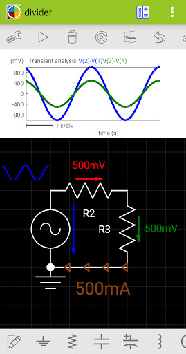
These tools allow easy creation of circuit diagrams and SPICE analysis of the created circuits. The simulator is focused on visual representation of simulated results, such that simulated voltages and currents can be placed elsewhere in the circuit, as a text or graph. Moreover, the magnitude and polarity of voltages and currents can be represented by visual indicators, so you can check the results quickly. All results can be additionally displayed on the top plot, where they can be explored using two cursors.
DC, AC and Transient analyses are supported.
The simulation can be run repeatedly (in Transient analysis) and results can be displayed consecutively with a user controlled speed (in all analysis types), or all simulation results are displayed immediately. When the results are shown consecutively, you can control parameters of circuit elements by the seek bar and see the change of results in real time.
In AC analysis, you can display the magnitude, real value, imaginary value and phase of voltages and currents.
The schematic editor supports undo and redo and also working with several selected elements. All elements except wires allow proper rotation and flipping of the text inside elements.
Supported elements: wire, ground, resistor, capacitor, polarized capacitor, inductor, DC voltage source, pulse source, sinusoidal source, DC current source, text, picture, diode, zener diode, LED, transistors (NPN, PNP, NMOS, PMOS, NJFET, PJFET), logic gates (NOT, AND, NAND, OR, NOR, XOR, XNOR), SR latch, D flip-flop, T flip-flop, JK flip-flop, operational amplifier, 555 timer, LM317, LM337, 7805, 7905, VCVS, VCCS, CCVS, CCCS, potentiometer, transformer, switch SPST, switch SPDT, open push-button, closed push-button, relay SPST, relay SPDT, crossover.
Screenshots and exporting the whole circuit are also supported.
Wires are drawn using autorouting or they can be drawn manually using singl